- Overview
- Modules
- Benefits of getting training with LCT
- Course Outcome
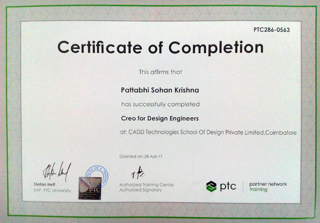
- Certification Sample
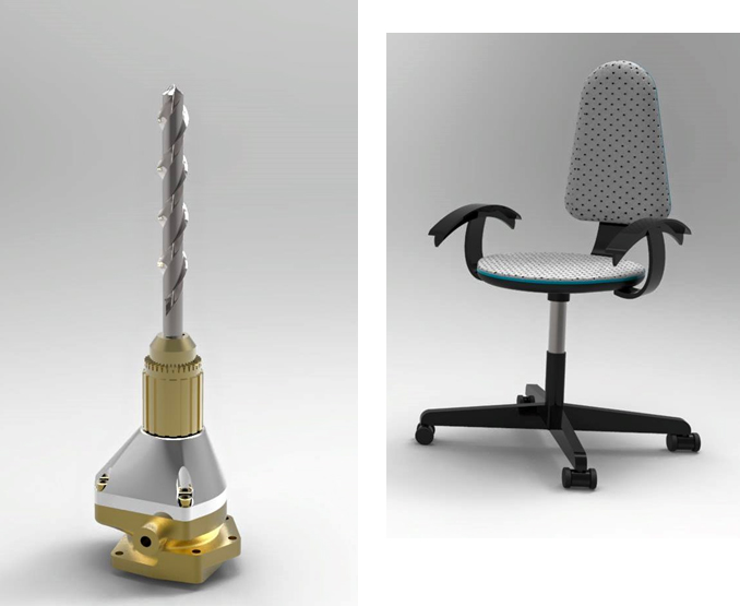
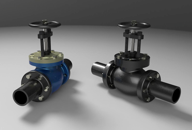
- Student's project
Overview:
Creo is a family or suite of design Software developed by Parametric Technology Corporation (PTC) in year 2011.The flagship application in the Creo Suite, Creo Parametric is the only software you need for 3D CAD. Design your entire product using both parametric and direct modeling. Interact directly with geometry, Suitable for infrequent CAD users.
Objective:
Creo Parametric, Direct, and Options Modular, lets users create 3D models by advanced CAD users as well as casual users and lets users do virtual prototyping to avoid creating multiple physical prototypes. It provides apps for 3D CAD parametric feature solid modeling, 3D direct modeling, 2D orthographic views, Finite Element Analysis and simulation, schematic design, technical illustrations, and viewing and visualization. Creo makes conversion of 2D to 3D, and usage of 3D geometry for simulation and analysis possible.
Pre-requisite:
Entire program carries modeling and other design applications. Students pursuing diploma and degree programs in Mechanical, Automobile and Aeronautical can enroll this program.
Duration:
108 Hours.- Introduction & Understanding to Creo Parametric Concepts
- Using Creo Parametric Interface
- Selecting of Geometry, Features, Models
- Editing of Geometry, Features, Models
- Sketcher Theory, Design Intent & Constraints
- Lines, Rectangles, Circles, Arcs, Ellipse
- Spline, Fillet, Chamfer, Text, Offset, Thicken, Palette
- Construction Geometry Theory, Geometry Tools
- Dimensioning Entities, Modifying Dimensions
- Sketch Feature, Sketch Setup, Sketch References, Entity from Edge
- Datum Features Theory, axes and planes
- Creating Extrudes
- Revolves, Ribs
- Creating Holes,
- Shells, Draft
- Creating Patterns
- Creating Rounds, Chamfers
- Using Layers
- Assembly & Constraint Theory, Default, Coincident Constraints
- Distance, Parallel, Normal, Angle, Automatic Constraints
- Exploding, Replacing Components
- Cross-Sections & Display Styles in Assemblies
- Advanced Selection, Creating Sweeps
- Blends, Rotational Blends
- Sweeps with Variable Sections
- Helical Sweeps
- Swept Blends
- Relations, Parameters
- Family Tables, Groups
- Copy, Mirror
- UDF
- Measuring, Inspecting Models & Seeking Help
- Capturing, Managing Design Intent
- Resolving Failures
- Introduction to Flexible Modeling
- Editing, Transformations
- Recognition in Flexible Modeling
- Component Interfaces
- Flexible Components, Restructuring
- Simplified Reps, Assembly Structure
- Skeletons, Copying model, Multiple Skeletons
- Sharing Skeleton Geometry, Creating and Placing Models
- Sheet metal Design Process
- Fundamentals, Creating Primary Wall Features
- Secondary Sheet metal Wall Features, Relief
- Bending, Transition To Bends
- Unbending, Bend Back, Flat States, Cuts
- Die Form, Punch Form, Rip Features
- Drawing Concepts, Ribbon, Formats, Sheets, General & Projection Views
- Editing Views, View Area, Detailed, Sectioned, Exploded Views
- Adding Model Details to Drawings
- Tolerance Information to Drawings
- Adding Notes, Symbols, Tables
- Report Tables, BOM Balloons
- Layers in Drawings, Drawing Environment
ATC's Part (Basic) & Assembly Modeling (Basic) - Creo :
ATC's Part (Adv) & Flexible Modeling - Creo:
ATC's Assembly (Adv), Sheet metal Modeling & Detailing - Creo:
Benefits of getting training with LCT
- Learning from a PTC Certified Instructor.
- Exposure to PTC training methodology & curriculum.
- Studying the finest practices and applications .
- Student name gets reflected on PTC website on course completion
- Each student will receive Personal Creo 2.0 Student version license software.
- PTC course material has been provide to the individuals.
Course Outcome
- Student will know how to sketch, model, validate design and visualize product design.
- Student will know how to do direct drafting, direct modeling as well as parametric 3D modeling.
- Student will know how to validate a design with engineering simulation and check whether the product design can meet the functional requirements.


